
Electric Working Principle of Induction Furnace Electrical Diagram
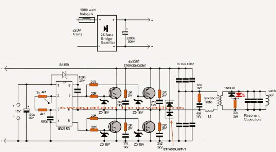
The working principle of the induction furnace electrical diagram is as follows: a three-phase bridge full-control rectifier circuit is used to rectify the alternating current into direct current, and after being smoothed by a reactor, it becomes a direct current power supply, and then through a single-phase inverter bridge, the direct current is inverted into a certain Single-phase intermediate frequency current with frequency (generally 1000 to 8000Hz). The load is composed of an induction coil and a compensation capacitor, which are connected into a parallel resonant circuit (it can also be connected in series. Generally, the IGBT power supply adopts series resonance, and of course, the IGBT power supply can also adopt parallel resonant circuit).
Under normal circumstances, the failure of the electric power supply of the induction furnace electrical diagram can be divided into two categories according to the failure phenomenon: it cannot be started at all and it cannot work normally after starting. As a general principle, when a fault occurs, a comprehensive inspection of the entire system should be carried out under the condition of power failure, which includes the following aspects:
(1) Induction furnace electrical diagram power supply: Use a multimeter to test whether there is electricity behind the main circuit switch (contactor) and the control fuse, which will rule out the possibility of these components being disconnected.
(2) Rectifier: The rectifier adopts a three-phase fully-controlled bridge rectifier circuit, which includes six fast fuses, six thyristors, six pulse transformers, and a freewheeling diode. There is a red indicator on the fast fuse. Normally, the indicator is retracted inside the shell. When the fast fuse is blown, it will pop out. Some fast fuse indicators are tighter. When the fast fuse is blown, it will be stuck inside. , so for the sake of reliability, you can use the on-off gear of a multimeter to test the fast fuse to determine whether it is blown.
The simple way to measure the thyristor is to measure its cathode-anode and gate-cathode resistance with a multimeter electric barrier (200Ω), and the thyristor does not need to be removed during measurement. Under normal circumstances, the resistance between the anode and the cathode should be infinite, and the gate-cathode resistance should be between 10-50Ω. If it is too large or too small, it indicates that the gate of the thyristor is invalid, and it will not be triggered to conduct.
The secondary side of the pulse transformer is connected to the thyristor, and the primary side is connected to the main control board. The resistance of the primary side is about 50Ω measured with a multimeter. Freewheeling diodes are generally not prone to failure. When checking, use a multimeter to block and measure its two ends. When the forward direction is forward, the multimeter shows that the junction voltage drop is about 500mV, and the reverse direction is blocked.
(3) Inverter: The inverter includes four fast thyristors and four pulse transformers, which can be checked according to the above method.
(4) Transformer: Each winding of each transformer should be connected. Generally, the resistance of the primary side is about tens of ohms, and the resistance of the second pole is several ohms. It should be noted that the primary side of the intermediate frequency voltage transformer is connected in parallel with the load, so its resistance value is zero.
(5) Capacitors: The electrothermal capacitors connected in parallel with the load may be broken down. Capacitors are generally installed in groups on capacitor racks. When checking, you should first determine the group where the broken-down capacitors are located. Disconnect the connection point between the busbar of each group of capacitors and the main busbar, and measure the resistance between the two busbars of each group of capacitors. Normally, it should be infinite. After confirming the bad group, disconnect the soft copper skin of each electric heating capacitor leading to the bus bar, and check one by one to find the breakdown capacitor. Each electric heating capacitor is composed of four cores, the outer shell is one pole, and the other pole is led to the end cap through four insulators. Generally, only one core is broken down, and the lead wire on this insulator is jumped off. The first capacitor can continue to be used, and its capacity is 3/4 of the original. Another failure of the capacitor is oil leakage, which generally does not affect the use, but pays attention to fire prevention.
The angle steel on which the capacitor is installed is insulated from the capacitor frame. If the insulation breakdown will cause the main circuit to be grounded, measure the resistance between the lead wire of the capacitor case and the capacitor frame to judge the insulation condition of this part.
(6) Water-cooled cable: The function of the water-cooled cable is to connect the induction furnace electrical diagram’s intermediate frequency power supply and the induction coil. It is twisted with each diameter Φ0.6-Ф0.8 copper wire. For a 500 kg electric furnace, the cable cross-sectional area is 480 square millimeters, and for a 250 kg electric furnace, the cable cross-sectional area is 300 to 400 square millimeters. Only when it is completely separated can it be correctly judged whether the core is broken.