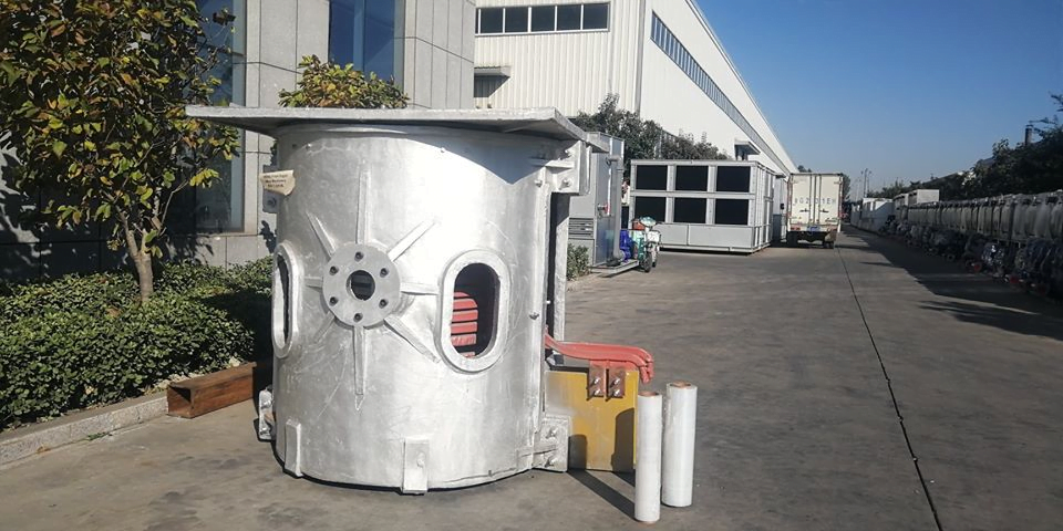
How is the induction melting furnace power calculation calculated?
The power of the induction melting furnace is an important indicator to measure the heating capacity of the induction melting furnace, and to a certain extent determines the heating speed and heating temperature of the induction melting furnace.
So, how is the power calculation of the induction melting furnace calculated?
What problems should be paid attention to in the power design of induction melting furnaces?
- The power of the induction melting furnace is different from the calculation of the operating power of general electromechanical equipment, but the basic principle is figured out, power = voltage × current, while the induction melting furnace power = DC voltage when estimating the power of the intermediate frequency electric furnace × DC current, so it seems that the power unit is Kw, which has a certain relationship with voltage and current.
- Design and manufacture of induction melting furnaces The calculation power of induction heating furnaces in the industry should be more detailed. When calculating the power of induction heating furnaces in the industry, it is first necessary to determine the material, heating time, productivity, heating temperature, and heating of the induction heating furnace. The weight of the workpiece is considered comprehensively based on years of experience, and the power of the induction heating furnace designed and calculated in this way is relatively accurate.
- In principle, the formula for calculating the power of an induction melting furnace is: the power of an induction melting furnace: P=(C×T×G) ÷ (0.24×S×η)
C=Specific heat of material (kcal/kg℃) G=Workpiece weight (kg) T=Heating temperature (℃)
t=time (S) η=heating efficiency (0.6)
Quenching Power Calculation of Intermediate Frequency Furnace
P=(1.5—2.5)×S
S= area of workpiece to be quenched (square centimeter)
the
Calculation of melting power of intermediate frequency furnace
P=T/2
T=electric furnace capacity (T)
Frequency calculation of intermediate frequency electric furnace
δ=4500/d2
4500=coefficient
d= radius of the workpiece
How much power factor should be used as compensation for the 300 kW intermediate frequency melting furnace?
The power grid stipulates that for transformers with a capacity of 200KVA or more, the power factor below 0.9 will be fined step by step, and the power factor above 0.9 will be rewarded step by step. This means that the lower the power factor, the more fines, and the higher the power factor, the higher the reward, up to 0.95.
The power factor of the medium frequency is generally around 0.78, and contains 2-7 harmonics. When the theoretical calculation is compensated until the power factor is 1, 188KVAR reactive power compensation equipment is required. The actual design selection can be selected between 150-200. In addition, the traditional Capacitor bank compensation is easily damaged due to harmonic problems under this working condition, and adding a reactor can only filter out a single harmonic, and the filtering effect is not good. It is recommended to use a low-voltage SVG to filter out harmonics while compensating reactive power.
What is the power of a 3-ton intermediate frequency furnace?
The power of 3T is generally around 2500kw, and the melting material is steel. If you are using other materials, you can call us directly for a consultation. The melting time is about 70 minutes per furnace.
What is the relationship between intermediate frequency power and intermediate frequency DC voltage and DC current?
The intermediate frequency power is the output power of the inverter, and the measurement is the power of the load (that is, the intermediate frequency quenching furnace if there is an output transformer, including the loss power of the output transformer).
The DC voltage is multiplied by the DC current to calculate the DC power. In addition to the intermediate frequency power, the DC power also includes the loss of the filter element (reactor or DC filter inductor), inverter thyristor or IGBT element, and the connecting busbar from the intermediate frequency output to the load.
So the intermediate frequency power is always smaller than the DC power. However, for a good intermediate frequency power supply, the difference between them (or the loss of the power supply) is not large, and it is reasonable within 5%.


One Response
P=(C×T×G) ÷ (0.24×S×η)
C=Specific heat of material (kcal/kg℃) G=Workpiece weight (kg) T=Heating temperature (℃)
t=time (S) η=heating efficiency (0.6)
Does Heating Temperature mean the change in temperature ie (T final – T initial) ?
Is the heating efficiency a constant or does it change based off the material being heated ?