Description
EAF Transformer
Furnace-duty power supply for electric arc steelmaking
Overview
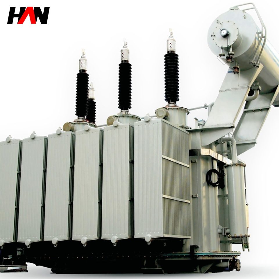
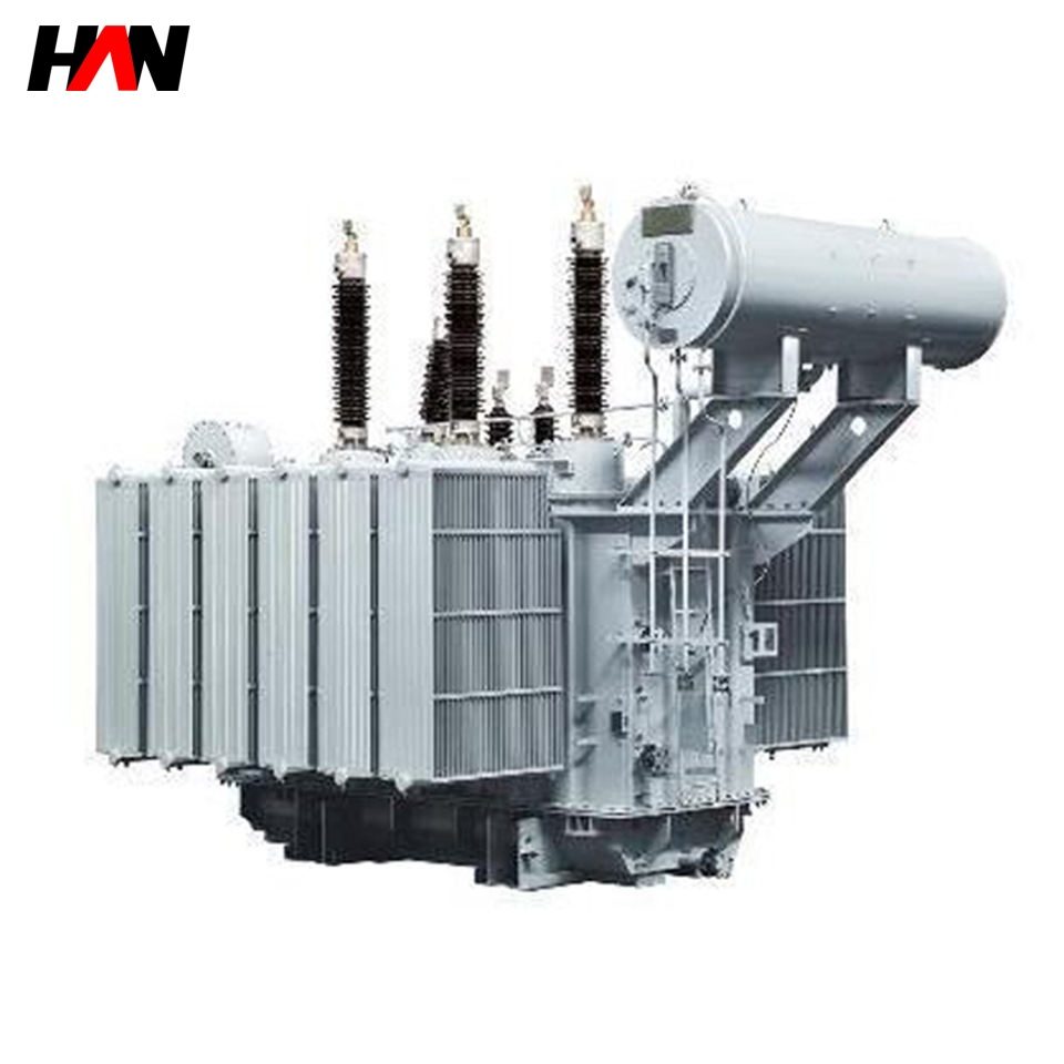
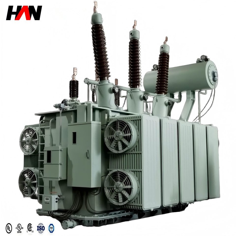
An EAF transformer is the piece of electrical equipment that sits between the plant’s high-voltage switchgear and the electrode column of an electric arc furnace. It takes the incoming 35 kV, 10 kV or 6 kV supply and steps it down to a few hundred volts, then delivers that energy as a secondary current measured in tens of thousands of amperes. The arc that melts the scrap is struck and extinguished several times per hour, so the transformer is asked to do something a distribution transformer never does: absorb repeated short circuits, ride through the inrush of a re-ignition, and change its output voltage continuously while the furnace is at full power.
In a short-process melt shop the transformer is the single component that fixes the ceiling of furnace productivity. Its rated capacity sets the power that can be delivered per heat, its impedance voltage sets how much of that power survives a scrap cave-in, and its tap range sets how the arc behaves during melting and during the flat-bath period. HANI Metallurgy builds these units for electric arc furnaces from 10 t to 150 t, and the same transformer family is applied to ladle furnaces and to DC arc furnaces with a rectifier downstream.
Technical Parameters
| Parameter | Unit | 12.5 MVA | 25 MVA | 40 MVA |
|---|---|---|---|---|
| Rated capacity | MVA | 12.5 | 25 | 40 |
| Primary voltage | kV | 35 / 10 | 35 | 35 |
| Secondary voltage range | V | 250 – 650 | 300 – 780 | 350 – 900 |
| Secondary current, lowest tap | kA | 28 | 48 | 66 |
| Impedance voltage | % | 7 – 9 | 8 – 10 | 9 – 11 |
| Tap changer | steps | 17, on-load | 17 – 21, on-load | 21, on-load |
| Vector group | — | Yd11 / Dd0 | Yd11 / Dd0 | Yd11 / Dd0 |
| Cooling | — | ONAN / ONAF | OFAF | OFAF / OFWF |
| Short-time overload | % | 20 for 2 h | 20 for 2 h | 20 for 2 h |
| Efficiency at full load | % | ≥ 98.6 | ≥ 99.0 | ≥ 99.2 |
| Design standard | — | IEC 60076-1 / -2, GB 1094.1 | ||
Typical values for reference. Final ratings, impedance and tap schedule are fixed on the nameplate and the approved project datasheet.
How It Works Under Furnace Duty
The load curve of an arc furnace falls into three phases. During bore-in the electrodes strike into cold scrap, the arc is unstable and the current swings far above its mean value. During melting the arc is long, the current is high and the furnace draws reactive power that pulls the supply voltage down. During the flat bath the arc is short and stable, and the furnace behaves more like a resistive load. A transformer sized only for the flat-bath power will be overloaded twice per heat; one sized for the bore-in peak will be oversized and run at poor efficiency for the rest of the campaign. The practical answer is a unit with thermal reserve and a tap schedule that keeps the arc at its optimum length in each phase.
Impedance voltage is the second lever. Raising it from 7 % to 10 % cuts the prospective short-circuit current at the electrode by roughly a quarter, which protects the electrode, the cable and the furnace structure, and it also damps the current swing that causes flicker on the upstream grid. The price is a small reduction in the power that reaches the arc, which is why impedance is chosen together with the short-net design rather than in isolation. The submerged arc furnace transformer follows the same logic with a different load profile: continuous, stable and with a large number of closely spaced taps.
Mechanically, the unit differs from a power transformer in three places. The low-voltage winding is built from many parallel copper strips, transposed along the coil height, because a single conductor would carry the full secondary current and would not fit. The tank and the lead exits are shielded with low-permeability steel or aluminium screens, because the stray field of a 40 kA lead would otherwise heat the tank wall. The core clamps and the winding bracing are dimensioned for the electromagnetic force of a through-fault, which rises with the square of the current and can reach hundreds of tonnes on a single coil.
Engineering notes
1. The tap changer works on the high-voltage side, so the low-voltage current stays high and the tap leads stay short.
2. A 20 % overload for two hours is a thermal allowance, not a continuous rating; the winding hot-spot limit still governs.
3. Winding temperature, oil temperature, Buchholz, pressure relief and DGA are the five signals that decide whether the unit can continue a campaign.
Key Advantages
- Thermal reserve for cyclic load: the oil circuit and the radiator bank are dimensioned for the melting phase, not the average, so the unit holds 20 % overload through a full heat without exceeding its hot-spot limit.
- Vacuum on-load tap changer: arcing takes place in a vacuum bottle instead of in oil, so the tap contacts stay clean through the tens of thousands of operations a steel plant accumulates in a year.
- Bracing designed for through-faults: coil, clamp and lead support are calculated for the peak electromagnetic force at the maximum short-circuit current, not for the rated current.
- Low stray loss at the tank: magnetic shielding around the low-voltage exits keeps tank-wall eddy losses down, which is where a high-current transformer usually loses its efficiency advantage.
- Interface built for the melt shop: the terminal arrangement, the cooling plant connections and the protection terminal box are laid out for a cable cellar or a busduct run to the short net, not for a substation yard.
Selection and Commissioning
- Start from the heat balance. Furnace capacity, tap-to-tap time and power-on time give the average power; the transformer rating is then set 15–25 % above that average to cover the melting peak.
- Fix the secondary voltage window. The top tap is chosen for the longest arc the scrap conditions allow, the bottom tap for the flat bath. A window narrower than 2:1 usually means the furnace is being asked to do two different jobs.
- Choose impedance with the short net. Total circuit reactance, not transformer impedance alone, decides arc stability; agree both numbers before the order is placed.
- Match protection to the duty. Instantaneous overcurrent is set above the bore-in peak, and the thermal image follows the transformer’s own heating curve rather than the breaker’s.
- Commission with a heat run. Oil and winding temperatures are logged through three complete heats; a rise that keeps climbing after the third heat points to a cooling or circulation problem, not to a setting.
- Plan the cooling water. OFAF and OFWF units need flow and temperature alarms wired into the furnace PLC, because a cooler trip at full power is a forced stop, not a derating.
Frequently Asked Questions
Q1: What is the difference between an EAF transformer and an ordinary power transformer?
A: Three things. The secondary voltage is low and the secondary current is very high, the voltage has to be adjustable on load over a wide range, and the unit is expected to survive repeated short circuits and a 20 % overload within every heat. Those requirements drive the winding layout, the bracing and the cooling design.
Q2: Can one transformer serve both the arc furnace and the ladle furnace?
A: Only if the two loads never run at the same time and the tap window suits both. In practice a ladle furnace transformer runs at a lower current with a steadier arc, so separate units give better efficiency and simpler protection.
Q3: How often does the tap changer operate?
A: In a two-shift melt shop, between 20 and 60 tap changes per day is normal, which adds up to well over 100 000 operations in a decade. That is why a vacuum on-load changer is specified rather than an off-circuit switch.
Q4: What information is needed to quote a unit?
A: Furnace capacity and tap-to-tap time, incoming voltage and fault level, required secondary voltage window, short-net layout, cooling water availability, altitude and ambient temperature, and the applicable standard. With these the rating, impedance and tap schedule can be fixed and the outline drawing issued.
Size the Transformer to the Furnace
Send the furnace capacity, incoming voltage and target tap-to-tap time, and HANI Metallurgy will return a rating, an impedance and a tap schedule for your melt shop.